Msd Shift Light Wiring

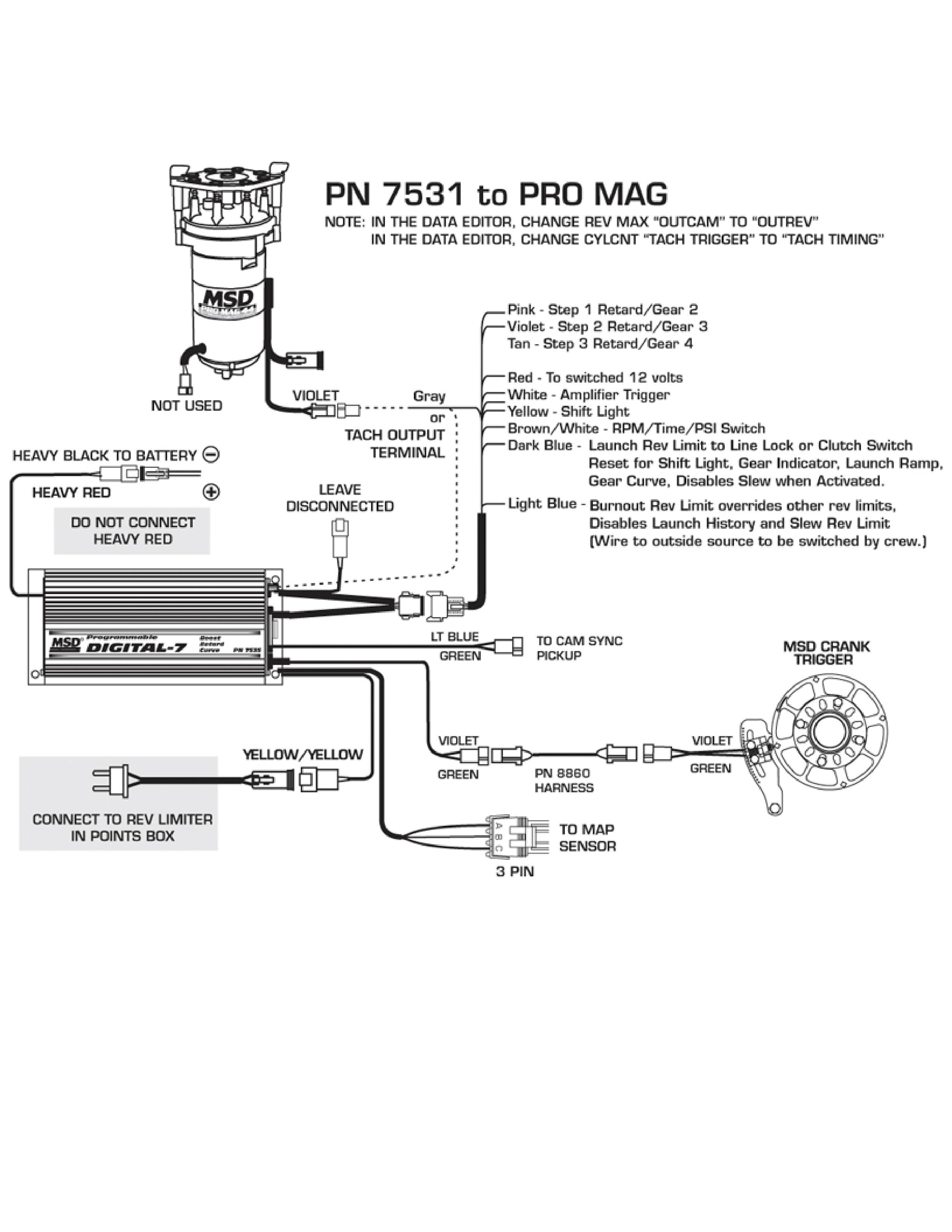
New Msd 7531 Wiring Diagram In 2020 Diagram Wire About Me Blog
How To Install An Msd Programmable Digital Shift Light On Your Mustang Americanmuscle
Msd Programmable Digital Shift Light Installation Instructions Americanmuscle
An Idiot S Guide To The Msd Shift Light Hyundai Genesis Forum

How To Install A Shift Light My Pro Street

Diagram Msd Digital 7 7531 Wiring Diagram Full Version Hd Quality Wiring Diagram Diagrams4u Jokergiochi It
To program it for use on other engines cut the correct wire loop s as shown in figure 1.
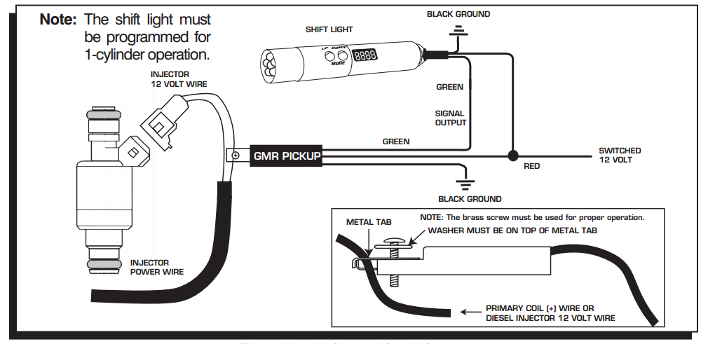
Msd shift light wiring. The msd digital shift light kit kit comes complete with the shift light and a gmr pickup for easy installation. Connect the black wire from the shift light to the black wire in the number four slot of the switch. The gmr pickup attaches to a current carrying wire without any splicing or cutting and turns the information into a 12 volt rpm signal that can be read by the shift light. Figure 1 cylinder select of the shift light.
Seal the cut wire ends with the sup plied heat shrink sleeves. Figure 1 cylinder select of the shift light. This is a 12v switched source. The terminal strip on the left side of the box is responsible for the power leads and the coil wires.
With the addition of an rpm activated switch you can use the two step to activate a shift light at different rpm the module selectors must be used with an msd soft touch rev control or a timing controller with a high speed retard module. To program it for use on other engines cut the correct wire loop s as shown in figure 1. Seal the cut wire ends with the supplied heat shrink sleeves. No rpm or retard modules are supplied.
Msd was the first company to develop and offer the multiple sparking capacitive discharge ignition for engines. The msd shift light is 4 5 l x 3 5 h with a 1 5 diameter lens. When 12 volts are applied the burnout rev limit is active. Connect the green wire from the msd shift light to the purple orange wire in the third slot of the switch.
No rpm modules are supplied. Yellow 1 shift light shift light output wire. Lt blue 4 burn out burnout rev limit. The line of msd 6 series ignitions are the most popular aftermarket ignitions in the world due to our race proven performance on the track and our reliability on the street.
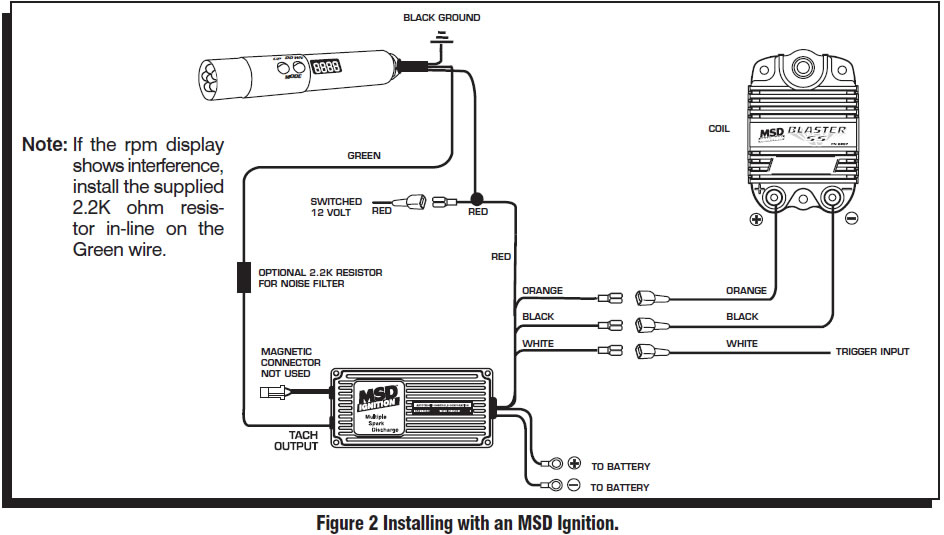
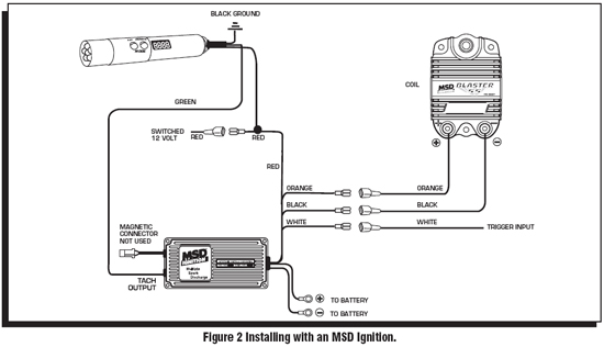
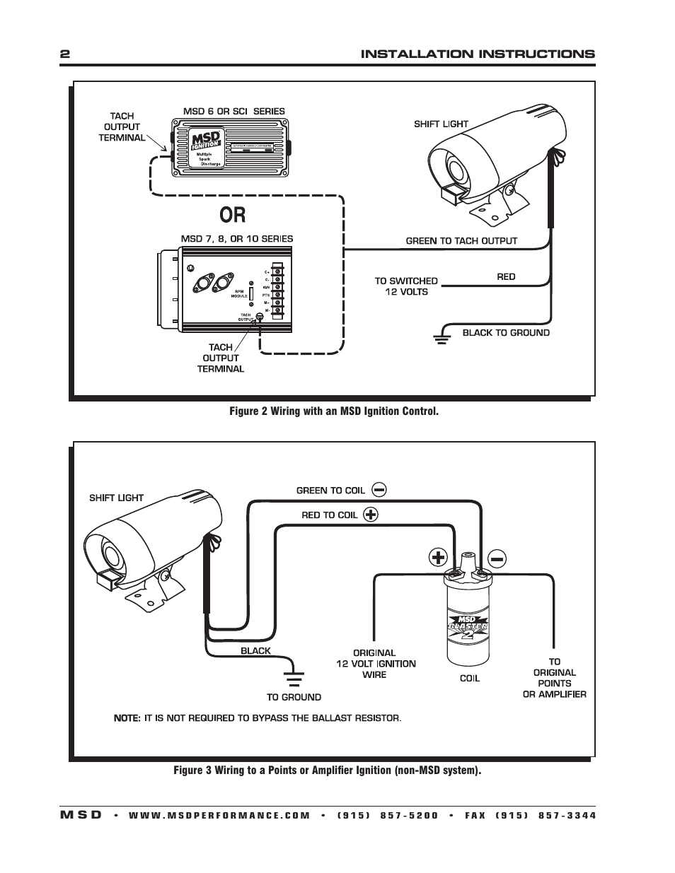
The shift light will work on 2 4 6 or 8 cylinder engines and will plug directly into the tach output on msd 6 sci 7 8 and 10 series ignitions or can be connected to the negative coil terminal when used with points or inductive type ignitions. Page 3 installation instructions figure 1 wiring the primary side of the ignition to points or magnetic pickup. The msd shift light is programmed for operation on 8 cylinder engines.
Msd 8952 Led Shift Light Installation User Manual Page 2 4

Msd 8963 Rpm Shift Light Installation Instructions Manualzz

Diagram In Pictures Database Msd Shift Light Wiring Diagram Just Download Or Read Wiring Diagram Venn Onyxum Com

Learn How To Tune Gm S 4l60e 4l65e Transmission Using Hp Tuners To Get The Drivability And Gear Shifting That You Want And T Transmission Tune Shift Schedule

Sponsored Ebay Msd Ignition 8963 Digital Shift Light Ebay Indicator Lights Msd

Holley Efi Terminator X Mpfi Tuner Kit W Ev6 Injector Harness Gm Ls2 Ls3 2007 2013 Gm Truck 4 8l 5 3l 6 0l V8 550 905t Holley Efi Gm Trucks Trucks

Pin On Electronics

Pin On Carro

Electronics Chevrolet Camaro Chevy Chevrolet Chevy Camaro

Msd Ignition 8226 Blaster Replacement Coil Gm Dual Connector Jegs Ignition Coil Msd Ignite

Msd Ignition Digital 6 Plus Faulty Msd Digital Msd Ignite

How Do I Install A Shift Light Pelican Parts Forums

Pin On Auto Accessories